

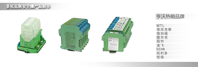
 产品直通车
产品直通车


MTL5042安全栅AI模拟量
- LED indicator Green: power indication Supply voltage 20 to 35V dc Maximum current consumption (with 20mA signal) 75mA at 24V 85mA at 20V 55mA at 35V Maximum power dissipation within unit (with 20mA signal) 1.3W at 24V Safety de
MTL5042 TEMPERATURE
CONVERTER
THC or RTD input
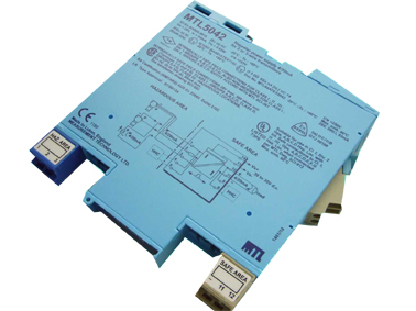
The MTL5042 converts a low-level dc signal from a temperature sensor
mounted in a hazardous area into a 4/20mA current for driving a
safe-area load. Software selectable features include linearisation,
ranging, monitoring, testing and tagging for eight thermocouple
types and 2-, 3- or 4-wire RTDs. For thermocouples requiring coldjunction compensation, the HAZ-CJC plug can be ordered with the
product, and includes an integral CJC sensor.
CONVERTER
THC or RTD input
The MTL5042 converts a low-level dc signal from a temperature sensor
mounted in a hazardous area into a 4/20mA current for driving a
safe-area load. Software selectable features include linearisation,
ranging, monitoring, testing and tagging for eight thermocouple
types and 2-, 3- or 4-wire RTDs. For thermocouples requiring coldjunction compensation, the HAZ-CJC plug can be ordered with the
product, and includes an integral CJC sensor.
LED indicator
Green: power indication
Supply voltage
20 to 35V dc
Maximum current consumption (with 20mA signal)
75mA at 24V
85mA at 20V
55mA at 35V
Maximum power dissipation within unit (with 20mA signal)
1.3W at 24V
Safety description
–75 to +75mV, or 0 to 400Ω (Input impedance 10MΩ)
Input signal span
3 to 150mV, or 10 to 400Ω
RTD excitation current
200µA nominal
Cold junction compensation
Automatic or selectable
Cold junction compensation error
≤1.0°C
Common mode rejection
120dB for 240V at 50Hz or 60Hz
Series mode rejection
40dB for 50Hz or 60Hz
Calibration accuracy (at 20°C)
(includes hysteresis, non-linearity and repeatability)
Inputs:
mV/THC: ±15µV or ±0.05% of input value
(whichever is greater)
RTD: ±80mΩ
Output: ±11µA
Temperature drift (typical)
Inputs:
mV/THC: ±0.003% of input value/°C
RTD: ±7mΩ/°C
Output: ±0.6µA/°C
Example of calibration accuracy and temperature drift
(RTD input)
Span: 250Ω
Accuracy: ± (0.08/250 + 11/16000) x 100%
=0.1% of span
Temperature drift: ± (0.007/250 x 16000 + 0.6) µA/°C
= ±1.0µA/°C
Safety drive on sensor burnout
Upscale, downscale, or off
Output range
4 to 20mA nominal (direct or reverse)
Maximum load resistance
600Ω
LED indicator
Green: one provided for power and status indication
Power requirement, Vs with 20mA signal
68mA at 24V
82mA at 20V
52mA at 35V
Power dissipation within unit with 20mA signal
1.5W at 24V
1.6W at 35V
安全栅应安装在非危险场所。
安全栅通往现场(危险场所)的软铜导线截面积必须大于0.5mm²。
连接导线的绝缘强度大于500V。
安全栅本安端(有蓝色标记)和非本安端电路配线,不得接错和混淆。本安导线宜选用蓝色作为本安标记。本安导线和非本安导线在汇线槽中应分开铺设,采用各自保护套管。安全栅的本安
侧,不允许混淆有其它电源,包括其它本安电路的电源。
安全栅与一次仪表组成本安安全防爆系统时,必须经国家指定的防爆检验机构检验认可。PH系列安全栅安全栅由国家防爆电气监督检验中心,给出的Co,Lo分布参数是相对与ⅡC级(氢气级)
的最大允许值对于ⅡB级环境可把该参数乘以3,对于ⅡA级环境可把该参数乘以8。传输线选用不同规格的电缆时,其本身的电缆参数应予高度重视,不得超过规定值。
对安全栅进行单独通电调试时,必须注意安全栅的型号、电源极性、电压等级及安全栅外壳接线端上的标号。
严禁用兆欧表测试隔离安全栅端子之间的绝缘性。若要检查系统线路绝缘性时,应先断开全部安全栅接线,否则会引起内部器件损坏。
SPECIFICATION
See also common specification
Number of channels
One
Signal source
Types J, K, T, E, R, S, B or N THCs to BS 4937
EMF input
2/3/4-wire platinum RTDs to BS 1904/DIN43760 (100Ω at 0°C)
Location of signal source
Zone 0, IIC, T4 hazardous area
Div.1, Group A, hazardous location
Input signal range
Safety description
Terminals 2 to 1 and 3:
28V, 300Ω, 93mA; Um = 250V rms or dc
Terminals 1 to 3:
Non-energy-storing apparatus ≤1.2V, ≤0.1A, ≤20µJ and ≤25mW;
can be connected without further certification into any IS loop
with an open-circuit voltage <28V
Note: Terminals 1 and 3 only support HART® communications in one direction
from field device to safe-area connections 11 and 12
产品直通车

